


产品详情
Hawke防爆连接器Hawke MKIV Controlex Ex connector
Hawke防爆连接器Hawke MKIV Controlex Ex connector
上海颐品自动化,:
Hawke防爆连接器Hawke MKIV Controlex Ex connector
Hawke防爆连接器Hawke MKIV Controlex Ex connector
上海颐品自动化,:
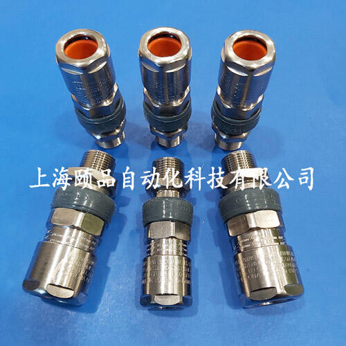
Hawke MKIV Controlex Ex connector
Hazardous Area Connector
Tamb: -40°C to +60°C. II2 GD Exdb IIC Gb, Extb IIIC Db T95 IP66, 67 & DTS01 deluge protected.
Overview
The 4th generation of Control connectors include many features and refinements as a result of consumer feedback, which makes them particularly suitable for control and low/medium power applications. The robust stainless steel body can hold up to 60 contacts and will accept conductor sizes ranging between 0.5mm² and 35mm², operating up to 125A and 750V.
Hawke MKIV Control![]() Features
Features
1、Easy Fieldwireable
Pin and socket inserts are numbered front and back to assist wiring and avoid termination errors. Crimp and solder inserts available.
2、Internal Keyway Spacer
Eases accessibility for termination as tube fitted after termination complete, along with allowing easy installation into the required keyed b (See 4)
3、Locking Pin
Optional locking pin provides the facility for mated connectors to be permanently locked, via the use of a padlock, ensuring they cannot be separated under load. (Padlock not supplied)
4、Keying Position
The unique visual 5 b insert keying system (3 on Ex16) along with the integral machined keyways prevent contact damage and ensures safe use by eliminating the possibility of misconnection of adjacent circuits.
5、Running Coupler
Allows the connector to be installed onto a pre-assembled cable gland. Connector is rear loading and includes locking engaging nut.
6、Acme Thread at Mating Interface
Unique ACME thread offers a smooth and quick fully mating b.
7、Fully Inspectable Flameproof Barrier
Provides direct inspection of the flameproof seal and offers users the peace of mind that the connector is safe for installation.
8、Anti-Rotation Device
Connector plugs and receptacles come complete with anti-rotation ring, which when fitted between the connector and gland, helps to eliminate the possibility of the gland loosening, locking this in b.
MKIV Control Connector Dimensions

The flameproof cap must be fitted to the connector before the power is restored to the disconnected circuit. The receptacle cap and plug cap are available in acetal and provide an IP rating of IP66/67. They may only be used when the socket or plug is not re-energised following disconnection. For connector plugs and connector receptacles cable glands are required to terminate incoming cables. Hawke recommend the ICG 653/UNIV cable gland is used.
| HAWKE Ex SERIES DIMENSIONS (MM) | ||||||
|---|---|---|---|---|---|---|
| Dimension | Ex16 | Ex25 | Ex32 | Ex40 | Ex50 | Ex63 |
| A | 127 | 152 | 152 | 152 | 152 | 148 |
| B | 105 | 128 | 129 | 129 | 129 | 126 |
| ØC | 36 | 46 | 53 | 60 | 66 | 83 |
| ØD | 37 | 49 | 57 | 65 | 76 | 90 |
| E | 128 | 152 | 152 | 152 | 152 | 152 |
| ØF | 32 | 45 | 51 | 59 | 70 | 83 |
| G | 15 | 15 | 15 | 15 | 15 | 15 |
| H (nominal) | 20 | 20 | 20 | 20 | 20 | 20 |
| J (Aperture bance hole) | 55 | 65 | 75 | 85 | 95 | 115 |
| * Thread L (1.5mm Pitch) | M25 | M32 | M40 | M50 | M63 | M75 |
| M | 54 | 54 | 56 | 56 | 56 | 56 |
| N A/F | 36 | 46 | 55 | 65 | 80 | 95 |
| R | 15 | 15 | 15 | 16 | 16 | 17 |
| S | 38 | 38 | 38 | 39 | 39 | 40 |
| ØT | 28 | 34 | 42 | 51 | 60 | 73 |
| U | 40 | 40 | 40 | 40 | 40 | 40 |
| Thread V (1.5mm Pitch) | M20 | M25 | M32 | M40 | M50 | M63 |
| X (nominal) | 54 | 70 | 70 | 70 | 70 | 67 |
| ØY | 66 | 76 | 83 | 91 | 102 | 117 |
| △ | 49 | 59 | 66 | 74 | 85 | 100 |
| ØZ | 87 | 99 | 105 | 117 | 129 | 147 |
| ? | 70 | 82 | 88 | 100 | 112 | 130 |
| * Bulkhead entry thread L can be adapted to other sizes. This may affect the overall length of unit. Contact us for details. | ||||||
MKIV Control Inserts

Cup Sizes and Selection Table
| CUP DIAMETERS | ||
|---|---|---|
| Insert Size | Internal Diameter of cup (mm) Nominal | |
| Soldered | Crimped | |
| 1.5mm² | 2 | 2 |
| 2.5mm² | 3 | 3 |
| 6mm² | 3.5 | 3.2 |
| 10mm² | 7 | 4 |
| 16mm² | 7 | 5 |
| 25mm² | 8 | 6.5 |
| 35mm² | 8 | 8.3 |
| INSERT SELECTION TABLE | |||||
|---|---|---|---|---|---|
| Shell Size 16 | Shell Size 25 | Shell Size 32 | Shell Size 40 | Shell Size 50 | Shell Size 63 |
| 3 x 1.5mm² + Earth | 4 x 1.5mm² + Earth | 12 x 1.5mm² + Earth | 24 x 1.5mm² + Earth | 37 x 1.5mm² + Earth | 49 x 1.5mm² + Earth |
| 4 x 1.5mm² + Earth | 9 x 1.5mm² + Earth | 19 x 1.5mm² + Earth | 30 x 1.5mm² + Earth | 27 x 2.5mm² + Earth | 60 x 1.5mm² + Earth |
| - | 12 x 1.5mm² + Earth | 10 x 2.5mm² + Earth | 19 x 2.5mm² + Earth | 13 x 6mm² + Earth | 37 x 2.5mm² + Earth |
| - | 4 x 2.5mm² + Earth | 12 x 2.5mm² + Earth | 4 x 25mm² + Earth | - | - |
| - | 7 x 2.5mm² + Earth | 4 x 6mm² + Earth | 4 x 35mm² + Earth | - | - |
| - | 4 x 6mm² + Earth | 6 x 6mm² + Earth | - | - | - |
| - | - | 3 x 10mm² + Earth | - | - | - |
| - | - | 4 x 10mm² + Earth | - | - | - |
| - | - | 3 x 16mm² + Earth | - | - | - |
| - | - | 4 x 16mm² + Earth | - | - | - |
| Note: Inserts for use in bulkhead receptacles are solder termination only, for contact sizes of 6mm² and above. Hawke Control 3rd & 4th generation Control Other voltages available on special request. | |||||
MKIV Control Calculations
To select the shell size of the connector, it is essential that you calculate the dissipated wattage of the arrangement. This ensures that the arrangement does not exceed the maximum permitted temperature classification with regard to the upper ambient temperature for the area of installation. (please refer to table 1 below for the maximum allowable dissipated wattage per connector size).
| TABLE 1 | ||||||
|---|---|---|---|---|---|---|
| Connector Size | Upper Ambient Temperature of +40°C | Upper Ambient Temperature of +50°C | Upper Ambient Temperature of +60°C | |||
| Temperature Class | Temperature Class | Temperature Class | ||||
| T6 | T5 | T6 | T5 | T6 | T5 | |
| Ex16 | 5W | 7W | 4W | 6W | 2.6W | 4.6W |
| Ex25 | 8W | 11W | 6W | 10W | 4W | 7W |
| Ex32 | 10.5W | 14.5W | 8W | 12W | 5.4W | 9W |
| Ex40 | 12W | 17W | 9W | 14W | 5.5W | 10.5W |
| Ex50 | 13W | 20W | 10W | 17W | 6.5W | 12.5W |
| Ex63 | 17W | 29W | 13W | 24W | 8.5W | 17W |
| Maximum allowable dissipated wattage | ||||||
| Other ambient temperature options can be extrapolated from table 1 above, or contact Hawke International for more inbation. | ||||||
| TABLE 2 | |||
|---|---|---|---|
| Contact Size | Combined Cable And Contact Resistance (Ohms) | Contact Current Rating | |
| Soldered | Crimped | ||
| 1.5mm² | 0.0166Ω | 0.0173Ω | 10 amps |
| 2.5mm² | 0.0102Ω | 0.0109Ω | 17 amps |
| 6mm² | 0.0047Ω | 0.0054Ω | 30 amps |
| 10mm² | 0.0027Ω | 0.0033Ω | 78 amps |
| 16mm² | 0.0018Ω | 0.0024Ω | 78 amps |
| 25mm² | 0.0012Ω | 0.0018Ω | 125 amps |
| 35mm² | 0.0009Ω | 0.0015Ω | 125 amps |
Dissipated Wattage Calculation
Equation definitions:
W = Dissipated wattage factor of the connector
N = The number of conductors to be terminated/number of contacts required. (Note: A contact comprises of a pin and socket).
I = The current requirement per contact. (Note: This must be equal to or less than the maximum current rating of the contact, as shown in table 2 above).
R = The combined cable and contact resistance (see table 2 above).
Values pertinent to these definitions must then be b into the relevant fields below to calculate the dissipated wattage (W) of your chosen arrangement:
| 1. W = N x I ² x R | |||
|---|---|---|---|
| N | I | R | Dissipated Wattage (Watts) W |
(Note: The results must be lower than the maximum figure shown in table 1 above, for the appropriate temperature class and ambient temperature).
e.g. T6 40°C ambient application with 9 x 1.5mm² conductors running at 7 amps.
N = 9 contacts
I = 7 amps
R = 0.0166 Ω (1.5mm² soldered combined cable and contact resistance)
Therefore W = 9 x 49 x 0.0166 = 7.32 watts.
Therefore an Ex25 Connector should be specified for this application as the shell size can accommodate the required 9 x 1.5mm² pin / socket inserts (see insert selection table) and the resultant dissipated wattage (7.32 watts) is below the maximum permitted 8 watts (see table 1 above).
This equation can also be transposed to facilitate the calculation of the maximum number of conductors permitted in your selected connector (calculator 2 below ) and the maximum allowable current within the upper ambient temperature of your b (calculator 3 below).
2.  | |||
|---|---|---|---|
| W | R | I | Maximum Number Of Conductors N |
3.  | |||
|---|---|---|---|
| W | N | R | Current (Amps) I |
| Note: The result must not exceed the maximum current rating of the contacts (see table 2 above) | |||
Note: Unless otherwise requested, connectors will be marked as T5 with an upper ambient temperature of +40°C.
Order Codes
Hawke International does not recommend the use of their ControlEx Connectors in applications where rigid PVC/SWA/PVC power cabling (typically to BS 6346 standards or equivalnts) is used in portable/semi-portable applications.
When ordering, select the relevant code from each block as shown in the example below:
Control![]() /Exd-32-S-CP-V-19 x 1.5-S-C-FL-FPC-P-R25-A-1-T
/Exd-32-S-CP-V-19 x 1.5-S-C-FL-FPC-P-R25-A-1-T
| Control | Select Code | Debion | Example Code |
|---|---|---|---|
| Protection | Exd | Flameproof | Exd |
| Shell Size | 16 | 16 | 32 |
| 25 | 25 | ||
| 32 | 32 | ||
| 40 | 40 | ||
| 50 | 50 | ||
| 63 | 63 | ||
| Material | S | Stainless Steel | S |
| Connector Style | CP | Connector Plug | CP |
| CR | Connector Receptacle | ||
| BR | Bulkhead Receptacle | ||
| Keying System | V | Variable Keyway (All) | V |
| F | Fixed Keyway (only available if purchasing terminated) | ||
| Number Of Contacts | See insert selection | 19 | |
| X | No Insert | ||
| Contact Size | See insert selection | 1.5 | |
| Insert Type | P | Pin | S |
| S | Socket | ||
| X | No Insert | ||
| Termination Style * Note: Inserts for use in Bulkhead receptacles are solder termination only for contact sizes of 6mm² and above. | S | Solder* | C |
| C | Crimp* | ||
| X | No Insert | ||
| Flange Type ♦ Note: CP or CR only - one per mating pair. | FL | Mounting Flange | FL |
| SF | Split Flange (can be retro fitted after termination) | ||
| Cap Type | FRC | Flameproof Receptacle Cap | FPC |
| FPC | Flameproof Plug Cap | ||
| PRC | Plastic Receptacle Cap | ||
| PPC | Plastic Plug Cap | ||
| Locking Pin ♦ | P | Locking Pin (only one required per mating pair) | P |
| Alternative Cable Gland Entry ♦ | R20 | Reduced Cable Gland Entry M20 (Ex25 only) | R25 |
| R25 | Reduced Cable Gland Entry M25 (Ex40 & Ex32 only) | ||
| R32 | Reduced Cable Gland Entry M32 (Ex50 & Ex40 only) | ||
| R40 | Reduced Cable Gland Entry M40 (Ex63 & Ex50 only) | ||
| R50 | Reduced Cable Gland Entry M50 (Ex63 only) | ||
| Certification | A | ATEX/IECEx/EAC/Inmetro | A |
| N | ATEX/IECEx/EAC/Inmetro/NEC 505 Voltage reduced to 600V | ||
| Ambient Rating and Temperature Class T5 +40°C will be supplied as standard if alternative not specified. | 1 | T5 +40°C Standard | 1 |
| 2 | T5 +50°C | ||
| 3 | T5 +60°C | ||
| 4 | T6 +40°C | ||
| 5 | T6 +50°C | ||
| 6 | T6 +60°C | ||
| Termination ♦ | T | Termination Required | T |
♦ If not required omit selection character from order code.
Find A Connector Modifier
Ordering Inbation
For ordering inbation and codes, please see order codes tab.
MKIV Control Calculations
To select the shell size of the connector, it is essential that you calculate the dissipated wattage of the arrangement. This ensures that the arrangement does not exceed the maximum permitted temperature classification with regard to the upper ambient temperature for the area of installation. (please refer to table 1 below for the maximum allowable dissipated wattage per connector size).
| TABLE 1 | ||||||
|---|---|---|---|---|---|---|
| Connector Size | Upper Ambient Temperature of +40°C | Upper Ambient Temperature of +50°C | Upper Ambient Temperature of +60°C | |||
| Temperature Class | Temperature Class | Temperature Class | ||||
| T6 | T5 | T6 | T5 | T6 | T5 | |
| Ex16 | 5W | 7W | 4W | 6W | 2.6W | 4.6W |
| Ex25 | 8W | 11W | 6W | 10W | 4W | 7W |
| Ex32 | 10.5W | 14.5W | 8W | 12W | 5.4W | 9W |
| Ex40 | 12W | 17W | 9W | 14W | 5.5W | 10.5W |
| Ex50 | 13W | 20W | 10W | 17W | 6.5W | 12.5W |
| Ex63 | 17W | 29W | 13W | 24W | 8.5W | 17W |
| Maximum allowable dissipated wattage | ||||||
| Other ambient temperature options can be extrapolated from table 1 above, or contact Hawke International for more inbation. | ||||||
| TABLE 2 | |||
|---|---|---|---|
| Contact Size | Combined Cable And Contact Resistance (Ohms) | Contact Current Rating | |
| Soldered | Crimped | ||
| 1.5mm² | 0.0166Ω | 0.0173Ω | 10 amps |
| 2.5mm² | 0.0102Ω | 0.0109Ω | 17 amps |
| 6mm² | 0.0047Ω | 0.0054Ω | 30 amps |
| 10mm² | 0.0027Ω | 0.0033Ω | 78 amps |
| 16mm² | 0.0018Ω | 0.0024Ω | 78 amps |
| 25mm² | 0.0012Ω | 0.0018Ω | 125 amps |
| 35mm² | 0.0009Ω | 0.0015Ω | 125 amps |
Dissipated Wattage Calculation
Equation definitions:
W = Dissipated wattage factor of the connector
N = The number of conductors to be terminated/number of contacts required. (Note: A contact comprises of a pin and socket).
I = The current requirement per contact. (Note: This must be equal to or less than the maximum current rating of the contact, as shown in table 2 above).
R = The combined cable and contact resistance (see table 2 above).
Values pertinent to these definitions must then be b into the relevant fields below to calculate the dissipated wattage (W) of your chosen arrangement:
| 1. W = N x I ² x R | |||
|---|---|---|---|
| N | I | R | Dissipated Wattage (Watts) W |
(Note: The results must be lower than the maximum figure shown in table 1 above, for the appropriate temperature class and ambient temperature).
e.g. T6 40°C ambient application with 9 x 1.5mm² conductors running at 7 amps.
N = 9 contacts
I = 7 amps
R = 0.0166 Ω (1.5mm² soldered combined cable and contact resistance)
Therefore W = 9 x 49 x 0.0166 = 7.32 watts.
Therefore an Ex25 Connector should be specified for this application as the shell size can accommodate the required 9 x 1.5mm² pin / socket inserts (see insert selection table) and the resultant dissipated wattage (7.32 watts) is below the maximum permitted 8 watts (see table 1 above).
This equation can also be transposed to facilitate the calculation of the maximum number of conductors permitted in your selected connector (calculator 2 below ) and the maximum allowable current within the upper ambient temperature of your b (calculator 3 below).
| 2. | |||
|---|---|---|---|
| W | R | I | Maximum Number Of Conductors N |
| 3. | |||
|---|---|---|---|
| W | N | R | Current (Amps) I |
| Note: The result must not exceed the maximum current rating of the contacts (see table 2 above) | |||
Note: Unless otherwise requested, connectors will be marked as T5 with an upper ambient temperature of +40°C.
Order Codes
Hawke International does not recommend the use of their ControlEx Connectors in applications where rigid PVC/SWA/PVC power cabling (typically to BS 6346 standards or equivalnts) is used in portable/semi-portable applications.
When ordering, select the relevant code from each block as shown in the example below:
Control![]() /Exd-32-S-CP-V-19 x 1.5-S-C-FL-FPC-P-R25-A-1-T
/Exd-32-S-CP-V-19 x 1.5-S-C-FL-FPC-P-R25-A-1-T
| Control | Select Code | Debion | Example Code |
|---|---|---|---|
| Protection | Exd | Flameproof | Exd |
| Shell Size | 16 | 16 | 32 |
| 25 | 25 | ||
| 32 | 32 | ||
| 40 | 40 | ||
| 50 | 50 | ||
| 63 | 63 | ||
| Material | S | Stainless Steel | S |
| Connector Style | CP | Connector Plug | CP |
| CR | Connector Receptacle | ||
| BR | Bulkhead Receptacle | ||
| Keying System | V | Variable Keyway (All) | V |
| F | Fixed Keyway (only available if purchasing terminated) | ||
| Number Of Contacts | See insert selection | 19 | |
| X | No Insert | ||
| Contact Size | See insert selection | 1.5 | |
| Insert Type | P | Pin | S |
| S | Socket | ||
| X | No Insert | ||
| Termination Style * Note: Inserts for use in Bulkhead receptacles are solder termination only for contact sizes of 6mm² and above. | S | Solder* | C |
| C | Crimp* | ||
| X | No Insert | ||
| Flange Type ♦ Note: CP or CR only - one per mating pair. | FL | Mounting Flange | FL |
| SF | Split Flange (can be retro fitted after termination) | ||
| Cap Type | FRC | Flameproof Receptacle Cap | FPC |
| FPC | Flameproof Plug Cap | ||
| PRC | Plastic Receptacle Cap | ||
| PPC | Plastic Plug Cap | ||
| Locking Pin ♦ | P | Locking Pin (only one required per mating pair) | P |
| Alternative Cable Gland Entry ♦ | R20 | Reduced Cable Gland Entry M20 (Ex25 only) | R25 |
| R25 | Reduced Cable Gland Entry M25 (Ex40 & Ex32 only) | ||
| R32 | Reduced Cable Gland Entry M32 (Ex50 & Ex40 only) | ||
| R40 | Reduced Cable Gland Entry M40 (Ex63 & Ex50 only) | ||
| R50 | Reduced Cable Gland Entry M50 (Ex63 only) | ||
| Certification | A | ATEX/IECEx/EAC/Inmetro | A |
| N | ATEX/IECEx/EAC/Inmetro/NEC 505 Voltage reduced to 600V | ||
| Ambient Rating and Temperature Class T5 +40°C will be supplied as standard if alternative not specified. | 1 | T5 +40°C Standard | 1 |
| 2 | T5 +50°C | ||
| 3 | T5 +60°C | ||
| 4 | T6 +40°C | ||
| 5 | T6 +50°C | ||
| 6 | T6 +60°C | ||
| Termination ♦ | T | Termination Required | T |
♦ If not required omit selection character from order code.
中国区分销商:
上海颐品自动化科技有限公司
Shanghai Epin Automation Co.,Ltd.
Website:www.epinautomation。。com
:sales@epinautomation.com
*: